Selecting the right coaxial cable is an important part of designing a reliable RF and microwave system. Even when transmitters, receivers, antennas, connectors and other RF components are carefully selected, an unsuitable cable can introduce signal loss, impedance mismatch, unwanted reflections and mechanical problems.
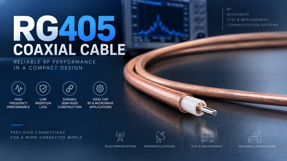
The RG405 Coaxial Cable is widely used in RF, microwave, laboratory, test and electronic applications where a compact semi-rigid cable construction and controlled electrical performance are required. Its small diameter makes it suitable for applications where space is limited, while its semi-rigid construction can provide stable routing and repeatable installation.
However, choosing an RG405 cable should not be based only on the cable designation. Frequency range, impedance, attenuation, power handling, connector configuration, bending requirements, environmental conditions and installation method should all be considered.
This guide explains the major factors to evaluate when selecting an RG405 Coaxial Cable for RF systems.
What Is RG405 Coaxial Cable?
RG405 is a commonly used designation for a small-diameter semi-rigid RF coaxial cable. It is designed for applications where controlled impedance, compact construction and predictable RF performance are important.
A typical coaxial cable consists of several primary components:
- Inner conductor
- Dielectric insulation
- Outer conductor or shield
- Protective outer surface, depending on construction
In many RG405 constructions, the cable uses a solid or semi-rigid metallic outer conductor and a PTFE-type dielectric. However, exact construction and specifications can vary between manufacturers and product variants.
The semi-rigid structure allows the cable to be formed into a particular routing configuration during installation. This makes it particularly useful inside RF equipment, test systems and compact electronic assemblies.
Why RG405 Coaxial Cable Is Used in RF Systems
RF systems operate across a wide range of frequencies, and cable selection becomes increasingly important as operating frequency increases. At higher frequencies, even relatively short cables can introduce measurable insertion loss and impedance discontinuities.
An appropriately selected RG405 Coaxial Cable can provide several advantages:
Compact Construction
RG405 is associated with a relatively small cable diameter, making it useful where installation space is restricted.
Controlled RF Performance
A properly manufactured RF coaxial cable maintains a controlled characteristic impedance throughout its length. This helps minimize signal reflections caused by impedance discontinuities.
Semi-Rigid Mechanical Structure
The semi-rigid construction allows the cable to be routed and formed into a specific shape. This can be beneficial inside RF assemblies where consistent cable positioning is required.
Suitable for High-Frequency Applications
RG405 cable variants are commonly used in RF and microwave assemblies. The exact usable frequency range should always be verified from the manufacturer’s datasheet before selecting the cable for a particular system.
Reliable Shielding
The metallic outer conductor provides shielding against electromagnetic interference and helps contain RF energy within the cable.
Key Factors When Choosing RG405 Coaxial Cable
Selecting the right RG405 Coaxial Cable requires evaluating the electrical, mechanical and environmental requirements of the application.
1. Check the Operating Frequency
Frequency is one of the most important factors when selecting an RF cable.
As frequency increases, cable attenuation generally becomes more significant. Manufacturing tolerances, connector quality, dielectric characteristics and conductor geometry can also have a greater effect on RF performance.
Before selecting an RG405 cable, determine:
- Minimum operating frequency
- Maximum operating frequency
- Required bandwidth
- Continuous-wave frequency
- Pulsed RF frequency, if applicable
The selected cable should have a specified frequency range that covers the complete operating range of the RF system.
For example, if a system operates across a broad microwave frequency range, selecting a cable based only on its physical similarity to another RG405 cable may not be sufficient. The manufacturer’s insertion-loss and VSWR specifications should be reviewed.
2. Verify 50 Ohm Impedance
Most RF systems using RG405 are designed around a 50 Ohm impedance.
The cable impedance should match the impedance of the connected RF components, such as:
- RF generators
- Spectrum analyzers
- Network analyzers
- Transmitters
- Receivers
- Antennas
- Amplifiers
- Filters
- RF switches
- Attenuators
- Couplers
Using components with mismatched impedance can increase reflections and degrade system performance.
When purchasing an RG405 Coaxial Cable, verify the nominal characteristic impedance from the manufacturer’s technical documentation rather than assuming it solely from the cable name.
3. Evaluate Insertion Loss and Attenuation
Cable loss is especially important in high-frequency RF systems.
Insertion loss represents the reduction in signal power as the signal travels through the cable. Cable attenuation generally increases with frequency and cable length.
When comparing RG405 cables, examine attenuation specifications at the actual frequencies used by your system.
A useful approach is to compare:
Cable attenuation per unit length × cable length
However, the complete signal path should also be considered because connectors, adapters and transitions introduce additional losses.
For precision measurement applications, even small losses can affect measurement accuracy.
4. Consider Cable Length Carefully
Shorter cables generally result in lower total transmission loss.
When designing an RF system, avoid unnecessary cable length while still maintaining appropriate mechanical routing and serviceability.
For example, a cable assembly connecting two RF modules should be long enough to avoid mechanical stress but should not contain excessive loops or unnecessary routing.
The total RF path should include:
- Cable length
- Connector losses
- Adapter losses
- Transitions
- Couplers
- Filters
- Other passive components
This provides a more realistic estimate of total insertion loss.
Read
5. Examine VSWR and Return Loss
VSWR and return loss describe how effectively RF energy is transferred through a transmission line without being reflected back toward the source.
A good-quality RG405 Coaxial Cable should maintain appropriate RF characteristics across its specified operating frequency range.
When selecting a cable assembly, pay attention not only to the cable itself but also to the quality of the connectors and terminations.
Poorly installed connectors can create impedance discontinuities even when the cable itself has excellent electrical characteristics.
For precision RF applications, review the manufacturer’s VSWR or return-loss specifications for the complete cable assembly whenever available.
6. Select the Appropriate Connector
The connector is an essential part of an RF cable assembly.
RG405 can be terminated with different RF connector types depending on the application. Possible connector configurations may include SMA and other miniature RF connectors, depending on the manufacturer and assembly design.
When choosing connectors, consider:
- Connector type
- Male or female configuration
- Interface standard
- Frequency rating
- Impedance
- Mounting configuration
- Mating cycles
- Environmental requirements
For example, an RG405 cable connecting two RF test instruments may require a different connector configuration from an internal RF module connection.
7. Consider Semi-Rigid Versus Flexible Construction
One of the most important mechanical considerations is whether your application actually requires a semi-rigid cable.
Semi-rigid RG405 cable is useful when the cable can be installed in a defined position and does not need frequent movement.
It is particularly suitable for:
- Internal RF equipment
- Microwave assemblies
- Laboratory instruments
- RF test fixtures
- Aerospace electronics
- Communication equipment
- Compact RF modules
If the cable must be repeatedly moved, bent or disconnected, a flexible RF cable may be more appropriate.
Therefore, cable selection should consider both electrical requirements and mechanical movement.
Read also: Reliable Retrofitting Contractors for Industrial Structures
8. Understand Minimum Bend Requirements
Semi-rigid cable should not be treated like ordinary flexible coaxial cable.
Excessive bending, repeated bending or improper forming can affect the geometry of the cable and potentially change its electrical performance.
When installing RG405, follow the manufacturer’s recommended:
- Minimum bend radius
- Forming method
- Bending direction
- Number of forming operations
- Installation procedure
A cable that looks mechanically acceptable may still experience performance degradation if it is improperly formed.
9. Evaluate Power Handling
Power handling is another important consideration when selecting an RG405 Coaxial Cable.
The maximum power a coaxial cable can safely transmit depends on multiple factors, including:
- Frequency
- Cable construction
- Ambient temperature
- Cable length
- VSWR
- Cooling conditions
- Dielectric characteristics
Power-handling specifications can therefore vary significantly between cable designs.
For high-power applications, never select a cable based solely on the RG405 designation. Use the manufacturer’s power-handling data for the actual frequency and operating conditions.
For pulsed applications, also check whether the manufacturer provides separate specifications for peak and average power.
10. Check the Operating Temperature
RF equipment may operate in environments ranging from controlled laboratories to industrial, outdoor, aerospace or transportation applications.
Before choosing an RG405 cable, determine the required temperature range.
Important parameters include:
- Minimum operating temperature
- Maximum operating temperature
- Storage temperature
- Temperature cycling requirements
The dielectric, conductor, connector and termination materials should all be suitable for the intended environment.
For demanding applications, the complete cable assembly should be evaluated rather than considering the cable alone.
11. Consider Material and Construction
The construction of an RG405 cable can influence both RF and mechanical performance.
Important construction parameters can include:
- Inner conductor material
- Dielectric material
- Outer conductor material
- Plating
- Shield construction
- Cable diameter
- Jacket or protective coating
- Connector material
For example, different conductor materials and plating combinations can influence conductivity, corrosion resistance, solderability and mechanical properties.
For high-frequency applications, the construction should be selected according to the required RF performance rather than simply choosing the lowest-cost option.
12. Look at Phase Stability
Phase stability can become important in precision RF and microwave systems.
Changes in cable position, temperature and mechanical stress can affect the electrical phase of a transmitted signal.
This matters particularly in:
- Vector network analyzer systems
- RF measurement equipment
- Phased-array systems
- Antenna measurement systems
- Microwave test fixtures
- Laboratory instrumentation
- Calibration assemblies
If phase repeatability is important, look for cable assemblies specifically designed and tested for phase stability.
13. Consider Shielding Requirements
The cable’s outer conductor helps protect the RF signal from external electromagnetic interference.
Good shielding is particularly important in environments containing:
- High-power electronics
- Motors
- Switching equipment
- Wireless transmitters
- Industrial machinery
- Multiple RF systems
For sensitive measurement systems, shielding effectiveness can influence the overall measurement environment.
The shielding specification should therefore be considered along with insertion loss, VSWR and connector performance.
14. Select the Correct Cable Assembly
In many applications, purchasing a complete RG405 cable assembly is more practical than purchasing bulk cable and terminating it independently.
A cable assembly can be specified according to:
- Cable type
- Length
- Connector A
- Connector B
- Connector gender
- Connector orientation
- Termination method
- Electrical performance
- Environmental requirements
For example, an RF test application may require a specific connector at each end and a defined cable length to connect two measurement instruments.
The assembly should be tested after termination whenever high measurement accuracy or repeatability is required.
RG405 Cable for RF Testing Applications
Testing and measurement systems place particularly demanding requirements on coaxial cables.
In a laboratory environment, the cable may be used between:
- Vector network analyzers
- Spectrum analyzers
- Signal generators
- RF power meters
- RF amplifiers
- Test fixtures
- Calibration standards
In these applications, cable performance can directly influence measurement results.
For this reason, engineers should consider insertion loss, return loss, phase stability, connector quality and repeatability when selecting an RG405 Coaxial Cable.
RG405 Coaxial Cable for Microwave Applications
Microwave systems are particularly sensitive to transmission-line performance.
As frequency increases, cable losses and impedance discontinuities can have a greater effect on system performance.
RG405 may be considered for compact microwave assemblies where its physical size and semi-rigid construction are suitable.
However, the exact frequency capability must be confirmed using the manufacturer’s published specifications.
For microwave designs, engineers should evaluate:
- Frequency range
- Insertion loss
- VSWR
- Return loss
- Phase performance
- Connector frequency rating
- Power handling
- Temperature range
RG405 for Internal RF Equipment
The compact structure of RG405 makes it useful for internal RF connections.
Inside an RF instrument, space can be limited and cable routing may need to follow a defined path.
Semi-rigid cable can be formed to connect components such as:
- Filters
- Amplifiers
- Oscillators
- RF switches
- Attenuators
- Couplers
- Connectors
- PCB-mounted RF components
The cable should be carefully formed to avoid unnecessary mechanical stress on the connectors.
RG405 Cable and Connector Compatibility
A common mistake when selecting RF cable is focusing on the cable while overlooking the connectors.
The complete RF path must be compatible.
Check the following:
| Parameter | What to Check |
| Impedance | Typically 50 Ohm for RF systems |
| Connector Type | Match both equipment interfaces |
| Connector Gender | Male or female as required |
| Frequency Rating | Suitable for maximum system frequency |
| VSWR | Appropriate for the application |
| Cable Length | Long enough for installation without excess |
| Power | Suitable for operating power |
| Temperature | Suitable for environmental conditions |
| Mechanical Design | Compatible with required routing |
RG405 Cable Selection for High-Frequency Signals
For high-frequency signals, cable selection should be based on measured or specified RF performance.
Important parameters include attenuation, return loss, VSWR and connector performance.
It is also important to consider the entire signal chain rather than looking at the cable in isolation.
For example:
RF Source → Connector → RG405 Cable → Adapter → Filter → RG405 Cable → RF Receiver
Every transition can contribute to the total insertion loss and reflection.
Therefore, selecting a high-quality cable alone does not guarantee optimal system performance if the connectors and interfaces are poorly matched.
Common Mistakes When Choosing RG405 Coaxial Cable
Choosing Based Only on Cable Diameter
A small cable may fit into a restricted space, but physical size alone does not determine whether it is appropriate for your RF application.
Ignoring Frequency
A cable suitable for one frequency range may not provide the required performance at a significantly higher frequency.
Selecting Excessive Cable Length
Unnecessary cable length can increase transmission loss.
Ignoring Connector Quality
Poorly terminated connectors can introduce reflections and additional loss.
Using Semi-Rigid Cable Where Frequent Flexing Is Required
Semi-rigid cable is generally intended for controlled installation rather than continuous movement.
Ignoring Temperature
Cable performance and material properties can change with temperature.
Assuming All RG405 Cables Have Identical Specifications
The RG405 designation does not eliminate manufacturer-specific differences. Construction, materials, electrical specifications and available cable assemblies can vary.
How to Compare Different RG405 Coaxial Cables
When comparing multiple RG405 products, create a technical comparison based on the requirements of your RF system.
Consider the following parameters:
| Specification | Why It Matters |
| Characteristic Impedance | Ensures compatibility with the RF system |
| Frequency Range | Determines usable operating bandwidth |
| Attenuation | Determines signal loss |
| VSWR | Indicates impedance matching performance |
| Return Loss | Indicates reflected signal performance |
| Power Handling | Determines safe RF power capability |
| Cable Diameter | Important for installation space |
| Connector Type | Determines equipment compatibility |
| Minimum Bend Radius | Important for mechanical installation |
| Temperature Range | Determines environmental suitability |
| Phase Stability | Important for precision RF measurements |
| Shielding | Helps control external interference |
| Cable Length | Affects total signal loss |
Step-by-Step RG405 Cable Selection Process
A practical selection process can be summarized in the following steps.
Step 1: Identify the RF Frequency
Determine the minimum and maximum operating frequencies.
Step 2: Confirm System Impedance
Verify that the RF system and cable use compatible characteristic impedance.
Step 3: Calculate Cable Length
Determine the required physical length while avoiding unnecessary cable.
Step 4: Determine Acceptable Loss
Establish the maximum cable attenuation that your system can tolerate.
Step 5: Determine Power Requirements
Check continuous and peak RF power requirements at the operating frequency.
Step 6: Select the Connector Configuration
Choose the correct connector type, gender and interface.
Step 7: Check Mechanical Requirements
Determine whether the cable will remain stationary or require repeated movement.
Step 8: Evaluate Environmental Conditions
Check temperature, humidity, vibration and other environmental requirements.
Step 9: Review Manufacturer Specifications
Compare the complete technical datasheet rather than relying only on the RG405 designation.
Step 10: Validate the Complete Assembly
For precision applications, verify the assembled cable’s electrical performance using appropriate RF measurement equipment.
RG405 Coaxial Cable vs Flexible RF Cable
The choice between RG405 and flexible RF cable depends largely on the application.
RG405 may be appropriate when the installation requires compact dimensions, controlled routing and a semi-rigid structure.
Flexible RF cable may be more suitable when frequent movement, repeated connection or mechanical flexibility is required.
The correct choice depends on the system’s electrical and mechanical requirements rather than simply the cable type.
Applications of RG405 Coaxial Cable
Common application areas for RG405-type coaxial cable include:
- RF test equipment
- Microwave test systems
- Laboratory instrumentation
- Communication equipment
- Wireless electronics
- RF modules
- Aerospace electronics
- Defense electronics
- Antenna systems
- Radar-related equipment
- Semiconductor test equipment
- RF measurement assemblies
- Signal generators
- Spectrum analyzer connections
- Vector network analyzer setups
The actual suitability should always be confirmed against the manufacturer’s specifications and the requirements of the specific application.
Why Cable Quality Matters in RF Systems
A coaxial cable may appear to be a relatively simple component, but it forms an important part of the RF signal path.
Cable quality can affect:
- Signal amplitude
- Insertion loss
- Reflections
- VSWR
- Phase
- Measurement repeatability
- Electromagnetic interference
- Long-term reliability
In high-frequency systems, small differences in cable and connector performance can become significant.
For this reason, engineers should consider the complete electrical and mechanical requirements before selecting an RG405 Coaxial Cable.
Final Checklist for Choosing RG405 Coaxial Cable
Before purchasing an RG405 cable, verify:
- Operating frequency
- Characteristic impedance
- Cable attenuation
- VSWR
- Return loss
- Required cable length
- RF power level
- Connector type
- Connector gender
- Connector frequency rating
- Cable diameter
- Minimum bend requirements
- Temperature range
- Shielding requirements
- Phase stability requirements
- Environmental conditions
- Required cable assembly configuration
- Manufacturer quality and test documentation
Conclusion
Choosing the right RG405 Coaxial Cable requires more than matching a cable designation with an application. Engineers should evaluate frequency, impedance, attenuation, VSWR, power handling, connector configuration, mechanical requirements, temperature range and environmental conditions.
RG405 can be a practical solution for compact RF and microwave assemblies where semi-rigid construction and controlled signal transmission are required. However, specifications can vary between manufacturers and cable constructions, so the final selection should always be based on the manufacturer’s current technical datasheet.
For demanding RF systems, selecting the cable and connector assembly as a complete transmission path can help ensure that electrical performance, mechanical installation and long-term reliability meet the requirements of the application.